I’m still using my 20$ soldering station which I use since I got started with electronics. Now it’s time for an upgrade. Weller® quality is exceptional, but also exceptionally expensive. Some guys designed an open source Weller® soldering station which is compatible with Weller® tips. This post describes the building process.
Bill of Materials
| Part | Quantity | MOQ | Supplier | Order number | Price / piece |
|---|---|---|---|---|---|
| PCB | 1 | 10 | dirtypcbs.com | 699 | $ 1.40 |
| Capacitor 0.1uF | 5 | 10 | farnell | 432210 | € 0.0106 |
| Resistor 10k | 3 | 100 | farnell | 2502397 | € 0.0021 |
| Resistor 1M | 2 | 100 | farnell | 2502399 | € 0.0021 |
| Resistor 1k | 10 | 100 | farnell | 2502396 | € 0.0021 |
| MOSFET BSN20 | 2 | 10 | farnell | 1081309 | € 0.332 |
| Capacitor 10uF | 2 | 1 | farnell | 1650980 | € 0.289 |
| 5V Regulator | 1 | 5 | farnell | 1467762 | € 0.309 |
| OPA336U | 1 | 1 | farnell | 1459587 | € 2.46 |
| Resistor 56k | 1 | 100 | farnell | 2502472 | € 0.0021 |
| Resistor 100R | 1 | 100 | farnell | 2502395 | € 0.0021 |
| MOSFET IRF7416 | 1 | 1 | conrad | 162476-29 | € 0.50 |
| Jackplug pcb | 1 | 1 | conrad | 734101-89 | € 1.35 |
| Jackplug tipholder | 1 | 1 | conrad | 595223-89 | € 1.46 |
| Jackplug male | 1 | 1 | conrad | 595197-89 | € 1.85 |
| Microphone cable | 2 | 1 | conrad | 608304-89 | € 2.30 |
| TFT 1.8" display | 1 | 1 | banggood | SKU103769 | € 4.68 |
| Arduino Pro Mini 5V | 1 | 1 | banggood | SKU066315 | € 2.65 |
| Power Supply 12V 8A | 1 | 1 | you | old computer | € 0.00 |
PCB Assembly
There was some confusion about the components, since the PCB I received was version 1.5 while the schematics on Github are version 1.6. The assembled board looks like this:
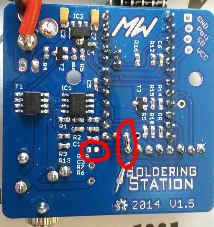
There is one important remark: I did not place R6 at the indicated pad, but between the display RST pin and the Arduino A6 pin. I did this because the display did not always boot. The reset pin was wired to +5V with a resistor, so always enabled. By wiring the RST pin to A6, the reset sequence can be controlled from the software. With this hack, I no longer experience problems with the display. edit: After hassling for hours, I figured out that it works best when the RST pin of the display is not connected at all…
The SMD components are placed according to the following table:
| Indicator | Component |
|---|---|
| C6 | 0.1uF capacitor |
| R12 | 10k resistor |
| R16 | 1M resistor |
| R14 | 10k resistor |
| R15 | 1k resistor |
| T3 | BSN20 mosfet |
| R8 | 1k resistor |
| R10 | 1k resistor |
| R9 | 1k resistor |
| C7 | 10uF tantalum capacitor |
| IC2 | 78L05 power regulator |
| C2 | 10uF tantalum capacitor |
| C4 | 0.1uF capacitor |
| R5 | 1k resistor |
| R11 | 10k resistor |
| T2 | BSN20 mosfet |
| R4 | 1k resistor |
| C5 | 0.1uF capacitor |
| R1 | 100R resistor |
| R3 | 1k resistor |
| R13 | 1M resistor |
| R2 | 56k resistor |
| C1 | 0.1uF capacitor |
| R18 | 1k resistor |
| C3 | 0.1uF capacitor |
| R7 | 1k resistor |
| R6 | DNP, see remark! |
Power Supply
An old computer power supply is used to provide 12V at more than 8 Amps. This saves the cost of buying a dedicated power supply and gives the power supply a second life.
The next post will describe how I built it all into a nice housing. I already bought this one from conrad: GSS05
Hi Bart,
I have also stumbled upon Weller home mad soldering station 2 months ago and decided to build it. Right now I’m still waiting for PCB’s and TFT display to arrive.
I’m curious how metal case work out for you (GSS05) as I have decided to put everything together (transformer + soldering station electronics)
I just can’t wait second (2/2) part of this build log !!! 🙂
Looking forward to hear from you !
Marek Grapiniak
I am half-way with the GSS05 but I have limited access to a CNC machine. Expecting to do part 2 within a month from now.
Hallo wo kriegt Mann die Platine PCB her.